
Diamond MX-2000N HF/VHF/UHF triplexor teardown
I recently bought two Diamond MX-2000N triplexors because at my current place I only have space for one RF cable from the shack to the roof. The idea is to have one triplexor in the shack and another one below the antennas. Before installing the triplexors I decided to bring them on the bench and check if the claimed performance is met by the devices.
Physical impression
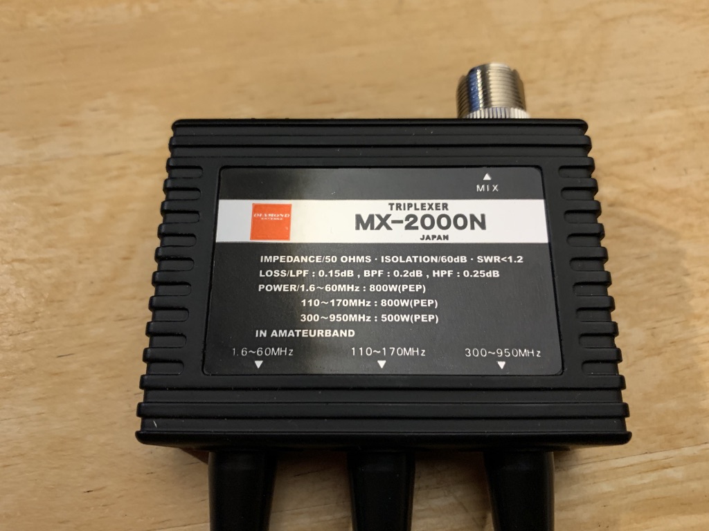
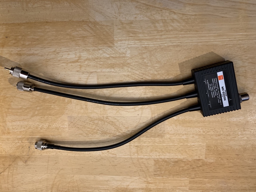
The MX-2000N triplexor comes in a solid metal case. On the bottom, it comes with pre-installed velcro tape. The MX-2000N has a PL-259 input plug and three output cables ending in PL-259 connectors (HF and VHF) or an N connector (UHF). The cables are about 30cm long and are made from 7mm 50 Ohm coax cable. The connectors seem to be well done - although I would have expected PTFE (Teflon) insulated connectors. Someone at Diamond had to save another 40 cents :-(. The overall physical impression is ok.
Specifications
The MX2000-N datasheet states the following performance claims:
| Band | Frequency range | Max power | Insertion loss | VSWR | Isolation |
|---|---|---|---|---|---|
| HF | 1.6 ~ 60MHz | 800W (PEP) | 0.15dB | < 1:1.2 | >= 60dB |
| VHF | 110 - 170MHz | 800W (PEP) | 0.20dB | < 1:1.2 | >= 60dB |
| UHF | 300 - 950MHz | 800W (PEP) | 0.25dB | < 1:1.2 | >= 60dB |
Measurement setup
I performed all measurements with an DG8SAQ Vector network analyzer. Before each measurement, the VNWA was calibrated on the plane of the test leads.
Insertion loss (S21)
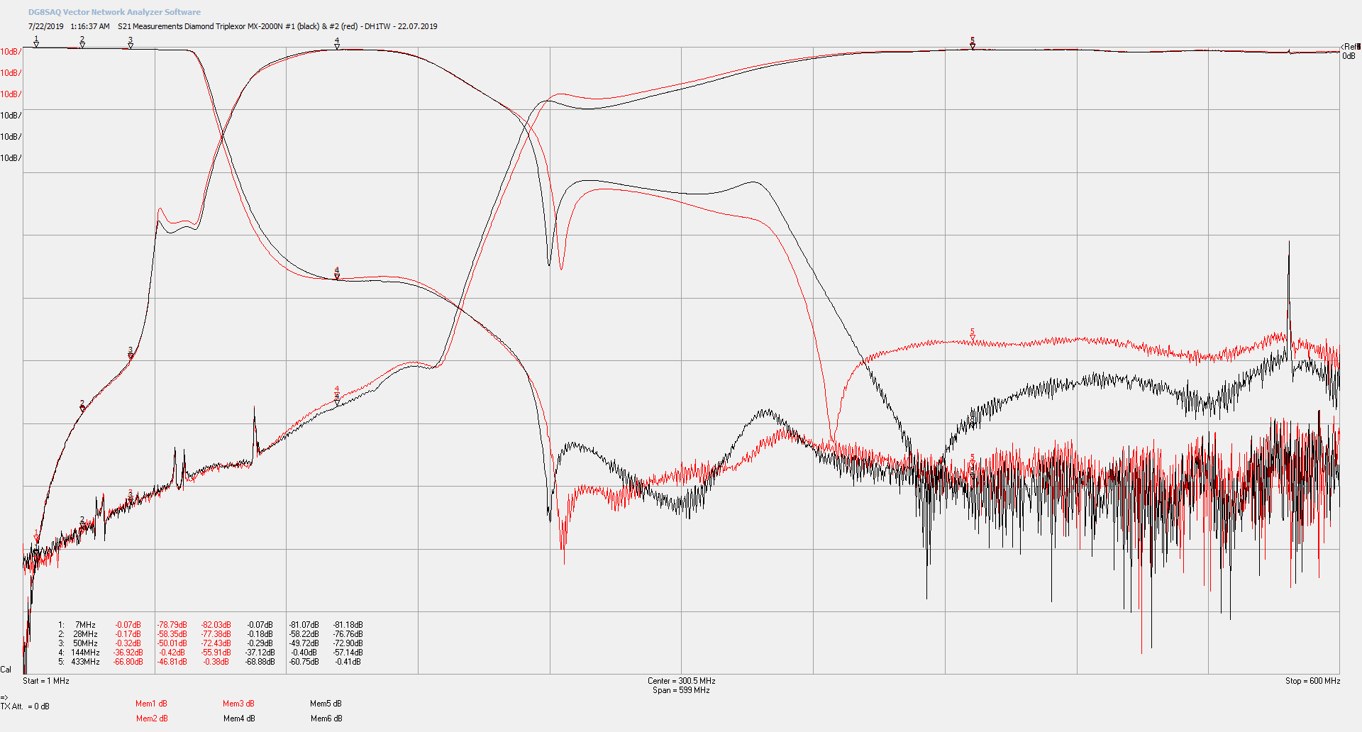
I measured the insertion loss of the two MX2000-N triplexors to check the claimed performance and the variation between the two (identical) devices. All unused ports were terminated with a 50 Ohm load.
Results
| Frequency | Insertion Loss (claimed) | Insertion loss (Device1) | Insertion loss (Device2) |
|---|---|---|---|
| 7.0 MHz | 0.15dB | 0.07dB | 0.07dB |
| 28 MHz | 0.15dB | 0.17dB | 0.18dB |
| 50 MHz | 0.15dB | 0.32dB | 0.29dB |
| 144 MHz | 0.20dB | 0.42dB | 0.40dB |
| 433 MHz | 0.25dB | 0.38dB | 0.41dB |
Up to approximately 30 MHz, the Diamond MX-2000Ns are within the specification. Above 30MHz, the measured insertion is higher than expected. The specified values in the datasheet are not met.
Return loss (S11 / VSWR)
Terminated ports
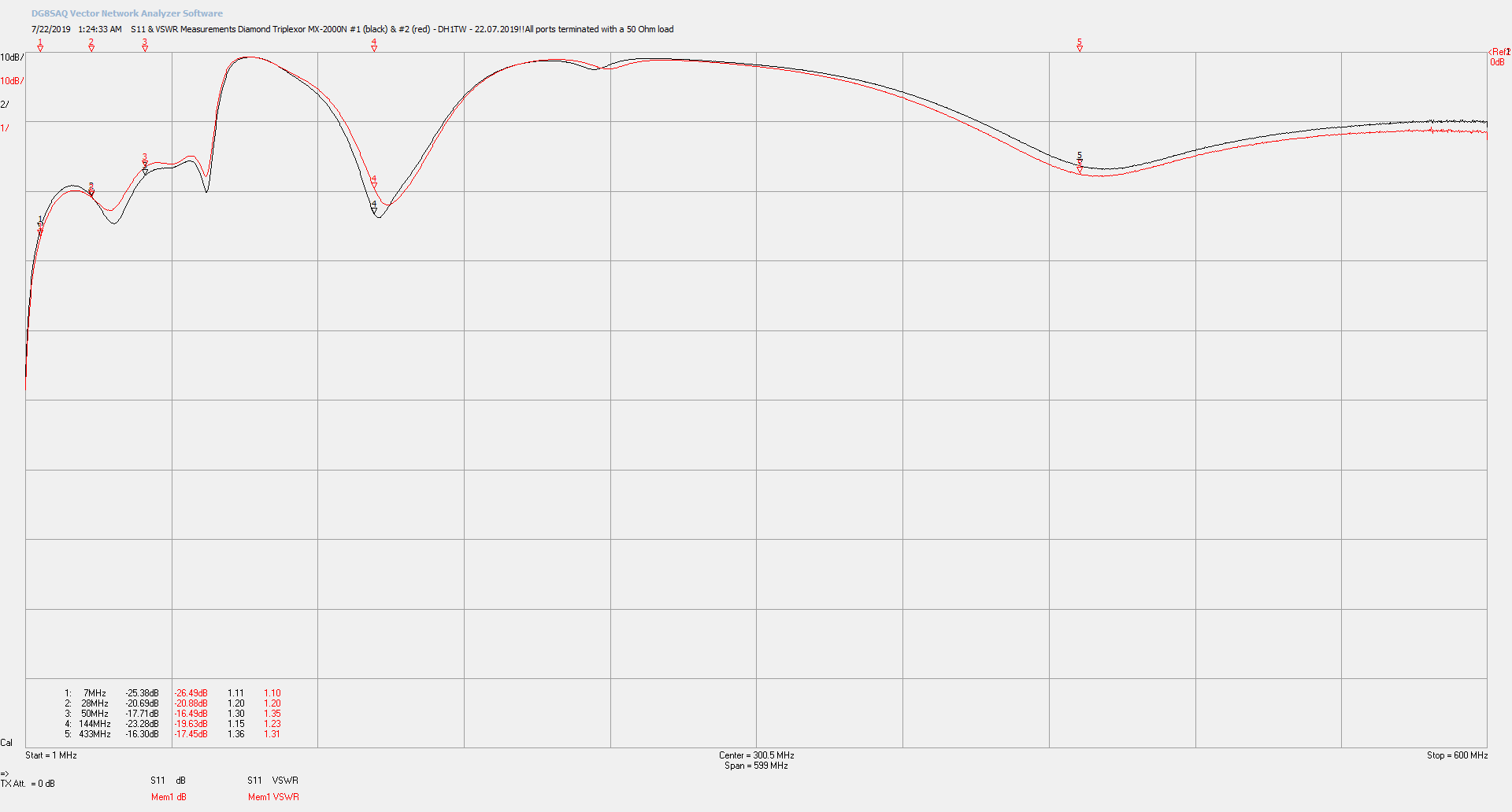
I measured the return loss of both devices with all three ports terminated with 50 Ohms.
Results
| Frequency | Return loss (claimed) | Return loss (Device1) | Return loss (Device2) |
|---|---|---|---|
| 7.0 MHz | < -20dB (<1:1.20) | -25.38dB (1:1.11) | -26.49dB (1:1.10) |
| 28 MHz | < -20dB (<1:1.20) | -20.69dB (1:1.20) | -20.88dB (1:1.20) |
| 50 MHz | < -20dB (<1:1.20) | -17.71dB (1:1.30) | -16.49dB (1:1.35) |
| 144 MHz | < -20dB (<1:1.20) | -23.28dB (1:1.15) | -19.63dB (1:1.23) |
| 433 MHz | < -20dB (<1:1.20) | -16.30dB (1:1.36) | -17.45dB (1:1.31) |
Close to the edges of the low pass filter (1-60MHz) the return loss is above the specified values. The high pass filter with the measurements done on 433 MHz also misses the specification.
Open ports
Depending on the filter design it might be necessary to have all ports terminated with 50 Ohms to work properly. I performed three measurements on Device1 with some unterminated ports.
- (TC1 black): HF 50Ohm terminated, VHF and UHF open
- (TC2 blue): HF & VHF 50 Ohm terminated, UHF open
- (TC3 red): HF, VHF, and UHF terminated with 50 Ohms

Results
| Frequency | Return loss (claimed) | Return loss (TC1) | Return loss (TC2) | Return loss (TC3) |
|---|---|---|---|---|
| 7.0 MHz | < -20dB (<1:1.20) | -25.47dB | -25.47dB | -25.48dB |
| 28 MHz | < -20dB (<1:1.20) | -20.28dB | -20.30dB | -20.29dB |
| 50 MHz | < -20dB (<1:1.20) | -17.98dB | -17.98dB | -17.99dB |
| 144 MHz | < -20dB (<1:1.20) | -0.73dB | -23.16dB | -23.20dB |
| 433 MHz | < -20dB (<1:1.20) | -0.25dB | -0.26dB | -16.66dB |
The measurements clearly show that it’s not necessary to have unused ports terminated. Although adding a small 50 Ohm load on the unused ports will certainly not harm.
Port Isolation
I measured the port isolation with the following three measurements:
- (TC1 black): HF - VHF
- (TC2 red): VHF - UHF
- (TC3 blue): HF - UHF
During the measurements, the unused ports were terminated with 50 Ohms.
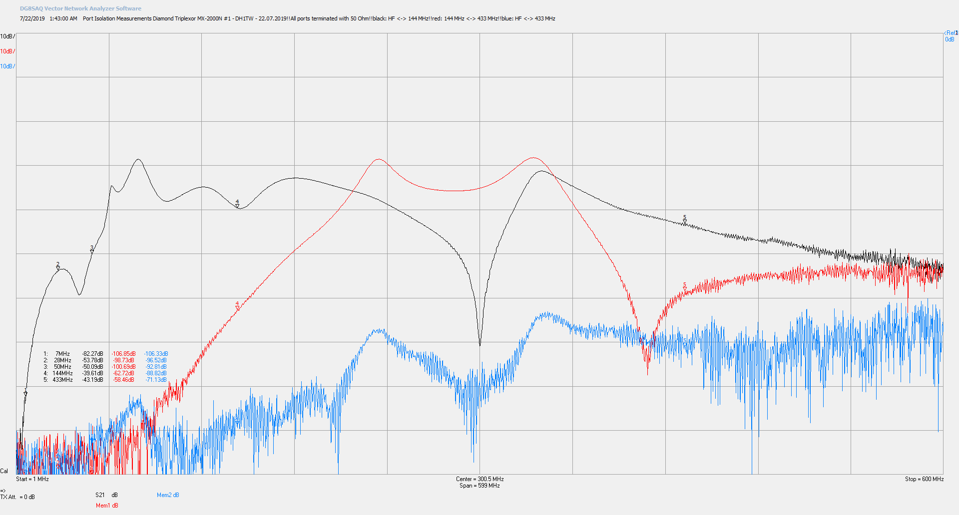
Results
| Frequency | Isolation (claimed) | Isolation (HF-VHF) | Isolation (VHF-UHF) | Return loss (HF-UHF) |
|---|---|---|---|---|
| 7.0 MHz | >= 60dB | 82.27dB | >90dB | |
| 28 MHz | >= 60dB | 53.78dB | >90dB | |
| 50 MHz | >= 60dB | 50.09dB | >90dB | |
| 144 MHz | >= 60dB | 39.61dB | 62.73dB | |
| 433 MHz | >= 60dB | 58.47dB | -71.13dB |
The Isolation between HF and VHF is below the specified 60dB. The values are not super worrisome, taking into account the power limitations of this triplexor and the additional filters in rx chain of an off-the-shelf receiver, however Diamond could have done better and at least met their specification.
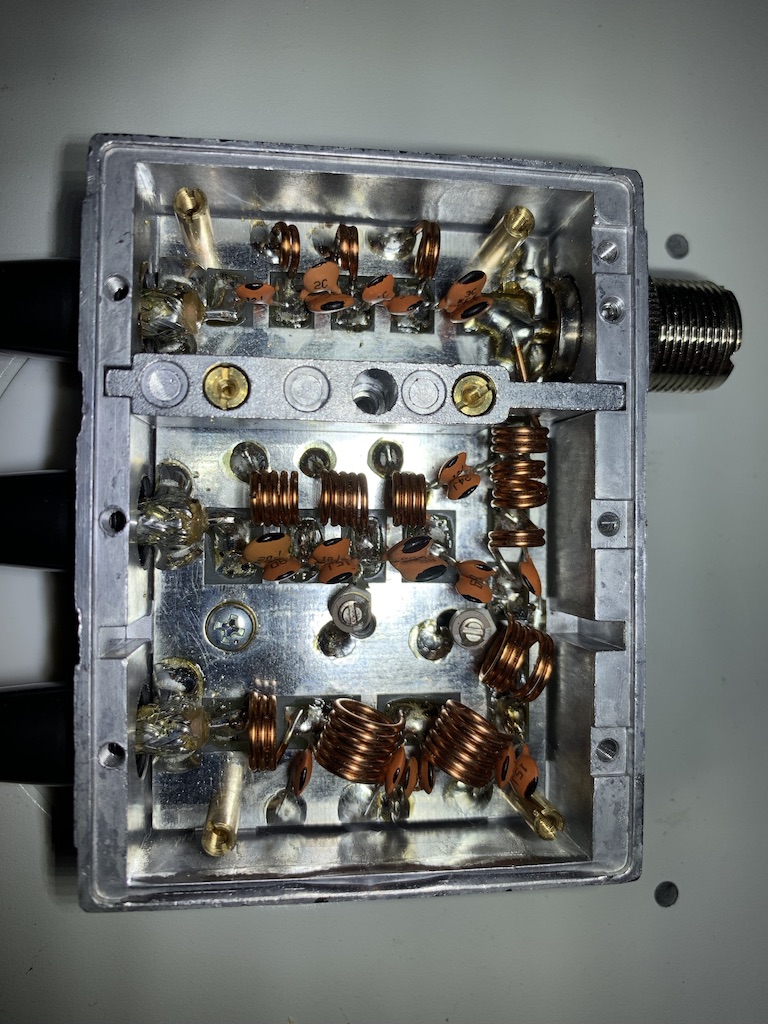
Teardown
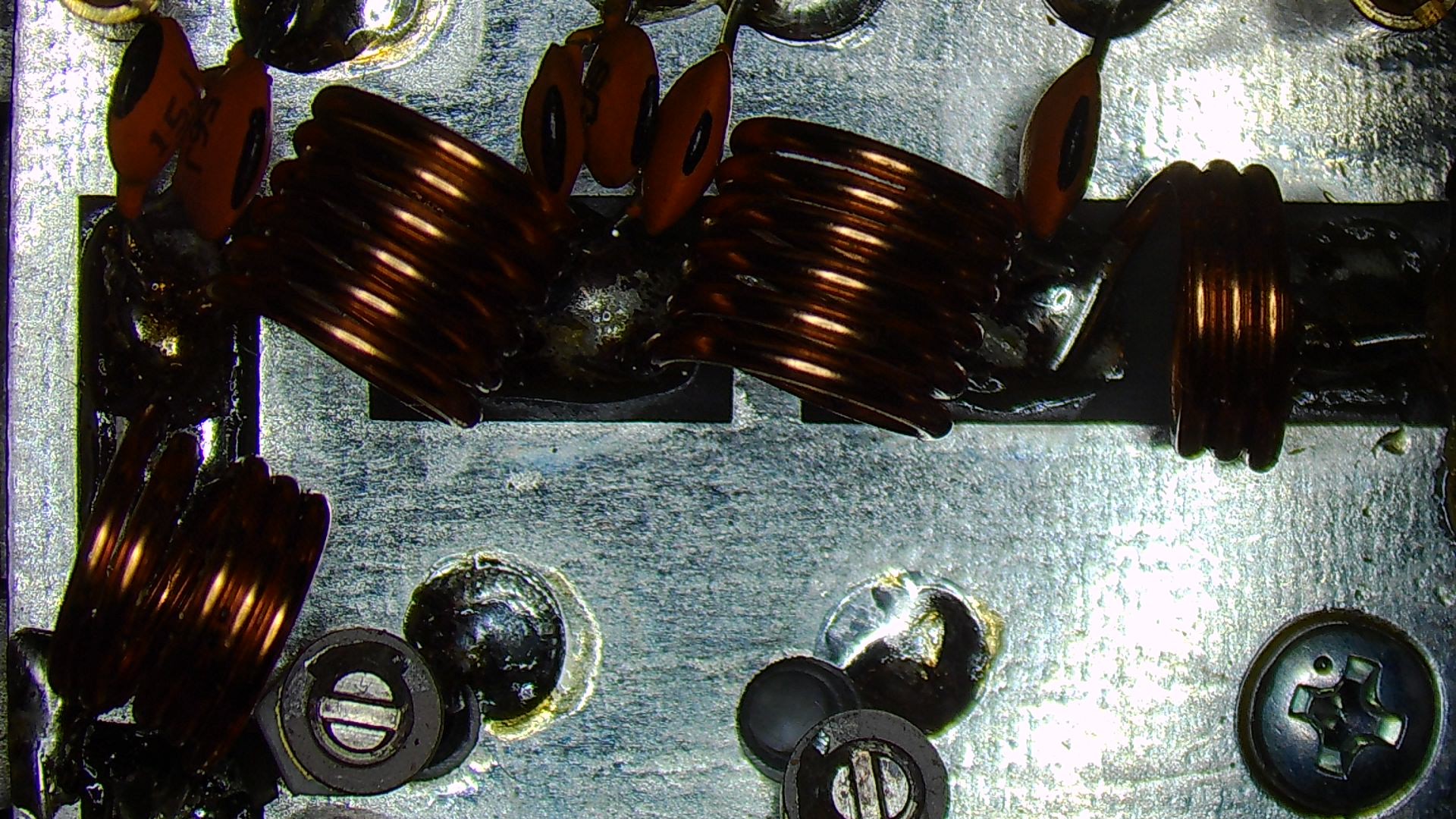
As a curious person, I wanted to have a look at the filter circuit. Find below a picture of the complete filter and some more detailed pictures of the individual HF/VHF/UHF filter.
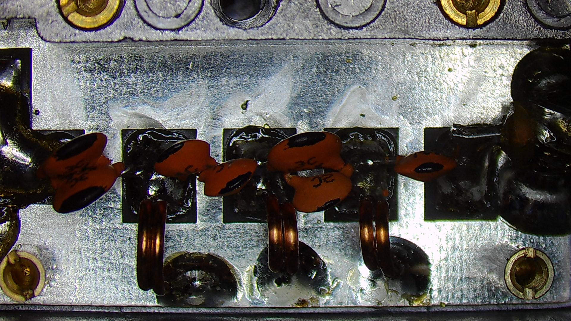
HF filter circuit
VHF filter circuit
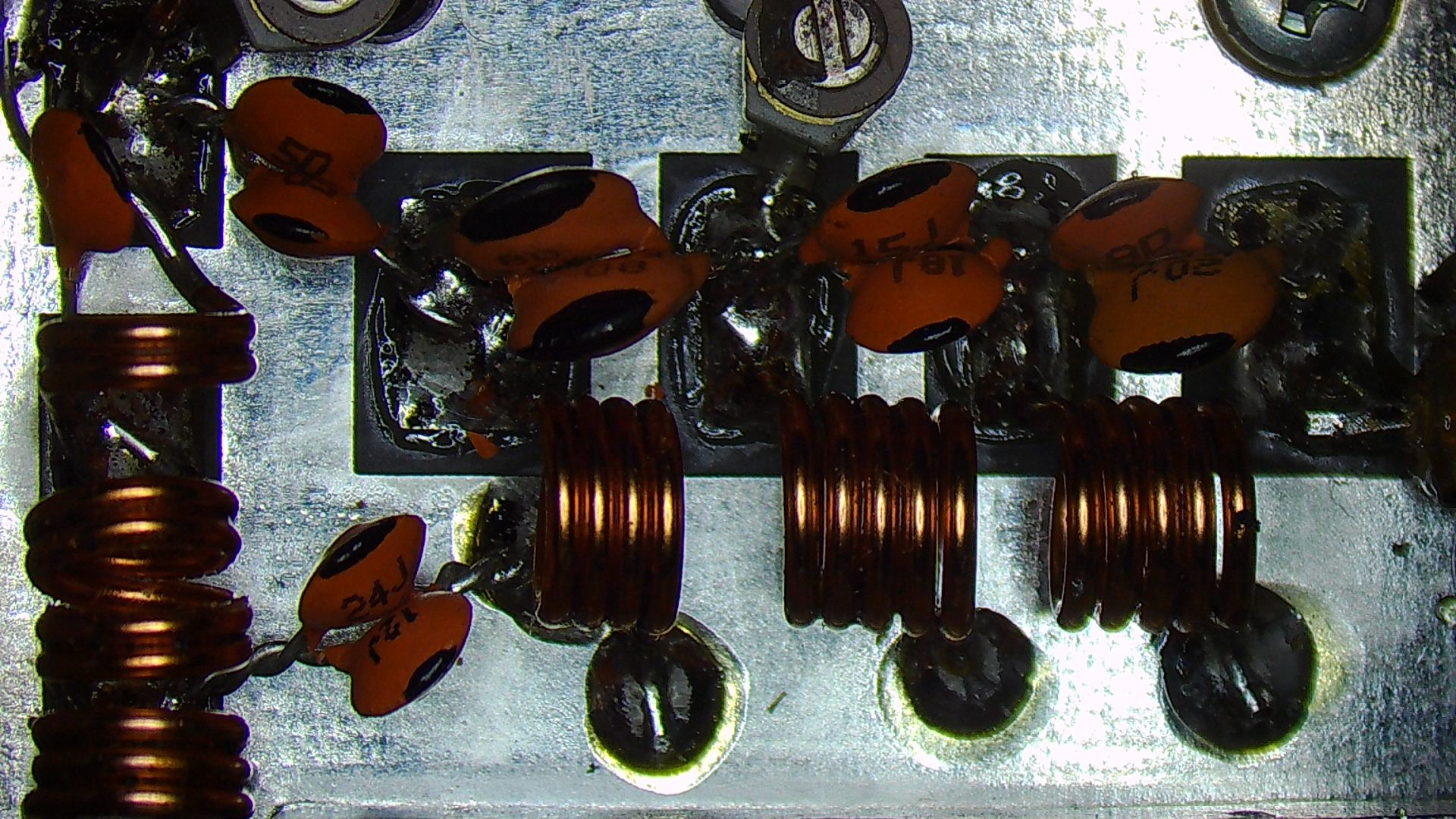
UHF filter circuit
Discussion
The Diamond MX-2000N is an inexpensive triplexor that is on the shelf available. As so often with amateur radio stuff, the specs on the datasheet look decent, but the actual device only partially meets them. In particular, the insertion loss should be better on the higher frequencies.
Whenever I read a power limit specified as “PEP”, it raises suspicions. Specifying Max Power in PEP is an implicit way to express that under key down the filter will blow up. After having a look at the components they confirmed my suspicion. The caps and coils are IMHO underrated to deal with 800W. As none of my rigs provide more than 100W and all of my antennas are properly matched, this is not a big deal for me. But again, I definitely wouldn’t apply 800W.
