ICOM IC7300 and IC9700 variable TX Delay verified
Both ICOM radios, the IC7300 and the IC9700 allow a variable transmission (TX) delay. This comes in handy if external peripherals like amplifiers and/or pre-amplifiers are used. These devices often have slow mechanical relays. It is good practice to wait until the complete transmission chain is ready before RF is applied. Out of curiosity, I measured and verified the adjustable tx delay on both radios.
Measurement setup
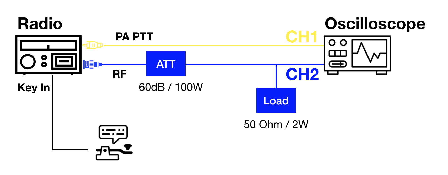
For this measurement, the two relevant signals from our radio(s) are PTT OUT and RF. The goal is to measure the time delay between the two signals. PTT OUT is used to key external devices like amplifiers. The exact name of this signal differs amongst radios and manufacturers, but the principle is always the same. The radio will pull down the signal to the Ground when the radio is keyed. RF is the generate Radio Frequency RF.

Figure 1: Schematic of the TX delay measurement setup
Measuring PTT OUT is quite simple. In the case of the Icom IC9700, the radio already provides a DC voltage on the signal line since PTT IN and PTT OUT share the same physical connector/pin (@ICOM WHY???). For the IC7300 we have to add positive DC voltage (inline with a >100k resistor) to simulate an external power amplifier. PTT OUT is tracked on CH1 (yellow trace) of the oscilloscope.
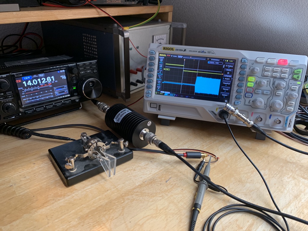
Probing an RF signal can be achieved in different ways. Since I have a 60dB / 100W attenuator, I choose to connect the radios RF OUT through the attenuator to the oscilloscope. Since my Rigol DS1054Z only has High Impedance inputs, I terminated the coax with a 2W / 50 Ohms resistor. The RF signal is tracked on CH2 (blue trace) of the oscilloscope.
As for the radio, the transmitter was put into CW and keyed a morse key.

Figure 2: TX delay measurement setup (IC7300)
Measurement results IC7300
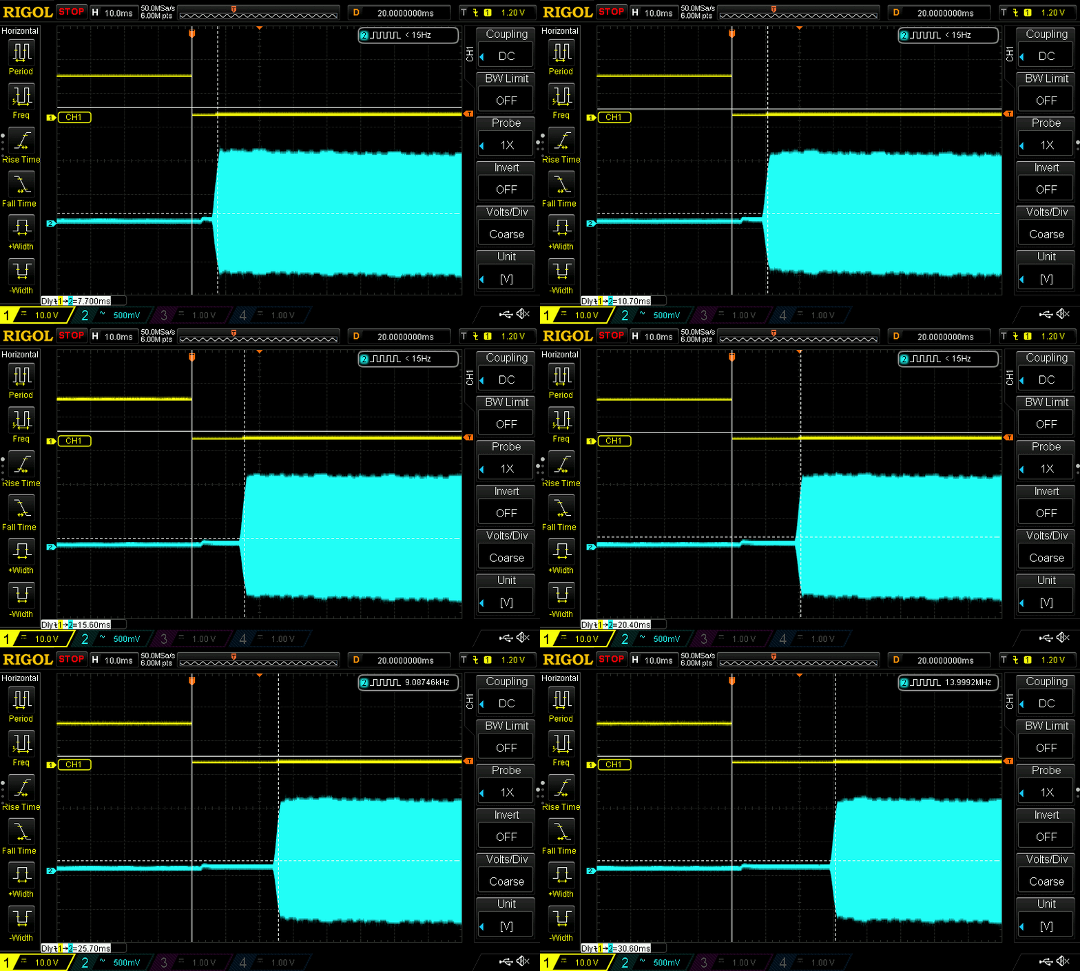
On the Icom IC7300, the user can define the TX delay in the onscreen menu by selecting MENU > SET > Function > TX Delay. While the TX Delay can be set individually for HF, 50M and 70M, only for HF all combinations were tested. In the result table below you can click on the corresponding result to load the detailed oscilloscope trace.
| Band | TX Delay (set) | TX Delay (measured) |
|---|---|---|
| HF | OFF | 7.7ms |
| HF | 10ms | 10.7ms |
| HF | 15ms | 15.6ms |
| HF | 20ms | 20.4ms |
| HF | 25ms | 25.7ms |
| HF | 30ms | 30.6ms |
In the figure below you can see the results stitched together in an animated gif.

Figure 3: IC7300 measured tx delay from 0-30ms
Measurement results IC9700
On the Icom IC9700, the user can also define the TX delay in the onscreen menu. The menu path is the same as on the IC7300 (MENU > SET > Function > TX Delay). While the TX Delay can be set individually for 144M, 433M and 1200M, only for 144 all combinations were tested.
| Band | TX Delay (set) | TX Delay (measured) |
|---|---|---|
| 144M | OFF | 9.1ms |
| 144M | 10ms | 11.8ms |
| 144M | 15ms | 17.0ms |
| 144M | 20ms | 21.7ms |
| 144M | 25ms | 26.6ms |
| 144M | 30ms | 31.7ms |
In the figure below you can see the results stitched together in an animated gif.

Figure 3: IC9700 measured tx delay from 0-30ms
Conclusion
On both radios, the variable TX delay works as expected. When the TX delay is set to 0ms/OFF, the radio still has an internal delay of a few milliseconds before power is applied to the antenna jack. This is fine and makes sense. It protects the internal RX/TX relay(s). On both radios, no major deviation was observed from the nominal and measured values.
ICOM has implemented the variable TX delay properly. It has been thoughtful to allow individual TX delays for different bands. However, I don’t understand why there is just a single physical PTT OUT signal. On HF this may still make sense since most modern amplifiers support HF + 6m. But on the IC9700 I would have expected one PTT_OUT signal per band. I’m not aware of any setup where it would make sense to key the 144MHz AND 433MHz AND 1296MHz amplifier at the same time. It just doesn’t make sense. There is plenty of space available on the backside of the radio. @ICOM, please fix this with the IC9700 MK2.