ST-Link & Blue Pill Development board
The ST-Link/v2 is an in-circuit debugger and programmer for the STM32 and STM8 microcontroller families. Due to its capabilities, it is an extremely popular device and clones are available from your preferred Chinese trading platform for less than 5 euros. I recently ordered a few of these cheap ST-Link/v2 clones for a new project. However, making them work was pretty frustrating. Read on to learn about the problem, the symptoms, and the (super) easy fix.
Connecting the ‘Blue Pill’
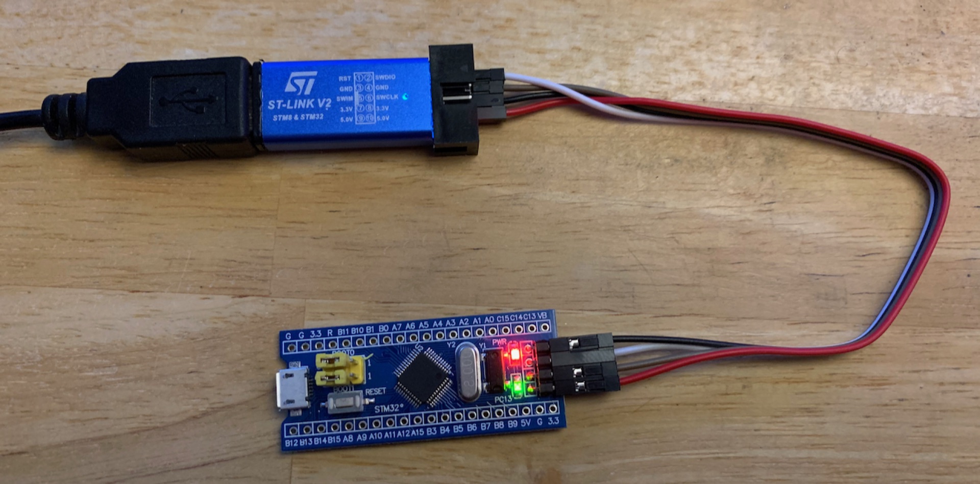
Over the years I’ve used occasionally the ‘Blue Pill’ which is a little development board, comparable in size with the better known Arduino Nano, but with a modern and more capable ARM Cortex M3 CPU (STM32F103C8T6).

Figure 1: ST-Link/v2 knock-off connected to a ‘Blue Pill’ development board
In the past, I used an original ST-Link/V2, but it became a victim of my last move. I couldn’t find it anymore. So I ordered a few clones on Aliexpress along with a bunch of ‘Blue Pill’ boards. The boards are certainly also knock-offs, although the CPU appears to be genuine.
Software tooling
I’m a big fan of Microsoft’s free and cross-platform Editor/IDE Visual Studio Code, but when it comes to ST microcontrollers I prefer to use their STM32CubeIDE. ST has come a long way integrating their stuff into Eclipse, but in 2020 it’s now working well, even on MacOS 😅.
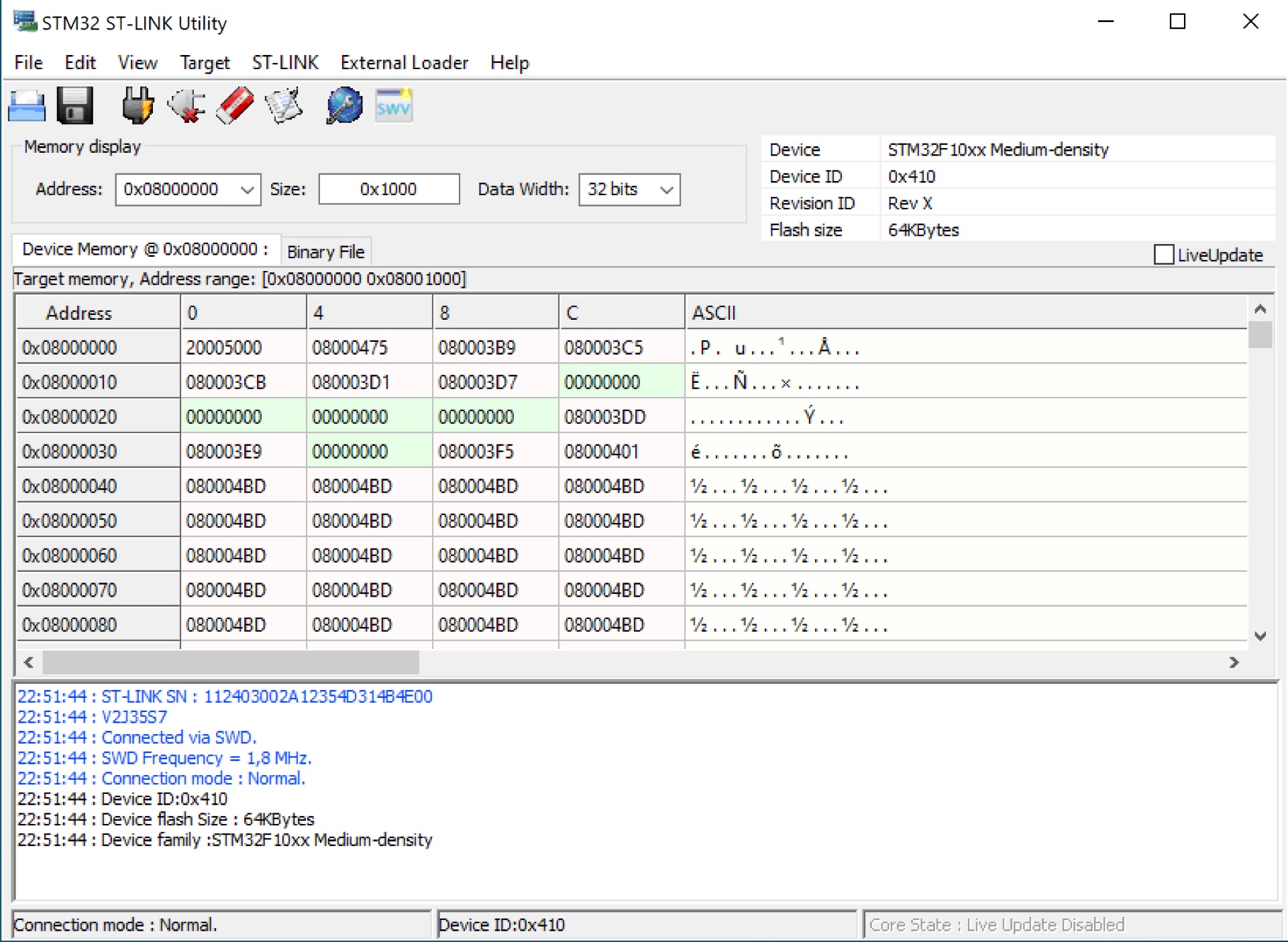
ST provides also some optional software tools for their microcontrollers. In particular, I found the STM32 ST-Link Utility (STSW-LINK004) to be quite helpful - although it’s only available for Windows.

Figure 2: Screenshot of the STM32 ST-Link Utility
The problem
The ST-Link/v2 has a 10 pin interface through which it interfaces with the development board. The pin-out diagram is printed on top of the ST-Link/v2. After connecting the two devices, I tried to upload a simple test program, but it just wouldn’t work and the error messages were also rather cryptic.
The symptoms
Despite that the ST-Link/v2 was properly recognized, I wasn’t able to connect or upload anything to the development board. Poking around with the ST-Link/v2 settings I was confronted with the following error messages over time:
- "Error in initializing ST-LINK device. Reason: No device found on target"
- "Can not connect to target! Please select "Connect Under Reset" mode from Target->Settings menu and try again. If you're trying to connect to a low-frequency application, please select a lower SWD Frequency mode from Target->Settings menu"
- "If the target is in low power mode, please enable "Debug in Low Power mode" option from Target->settings menu"
- "No device found on target"
- "No STM32 target found"
To ensure that this wasn’t a hardware issue, I tried of course several combinations of ST-Link/v2s and development boards. Unfortunately, none of them worked.
Success
Since none of my ‘Blue Pill’ development boards were recognized by none of the ST-Link/v2 programmers, I suspected a rather systematic error. Needless to say that I tried to google the error messages above, but none of the shown links were conclusive.
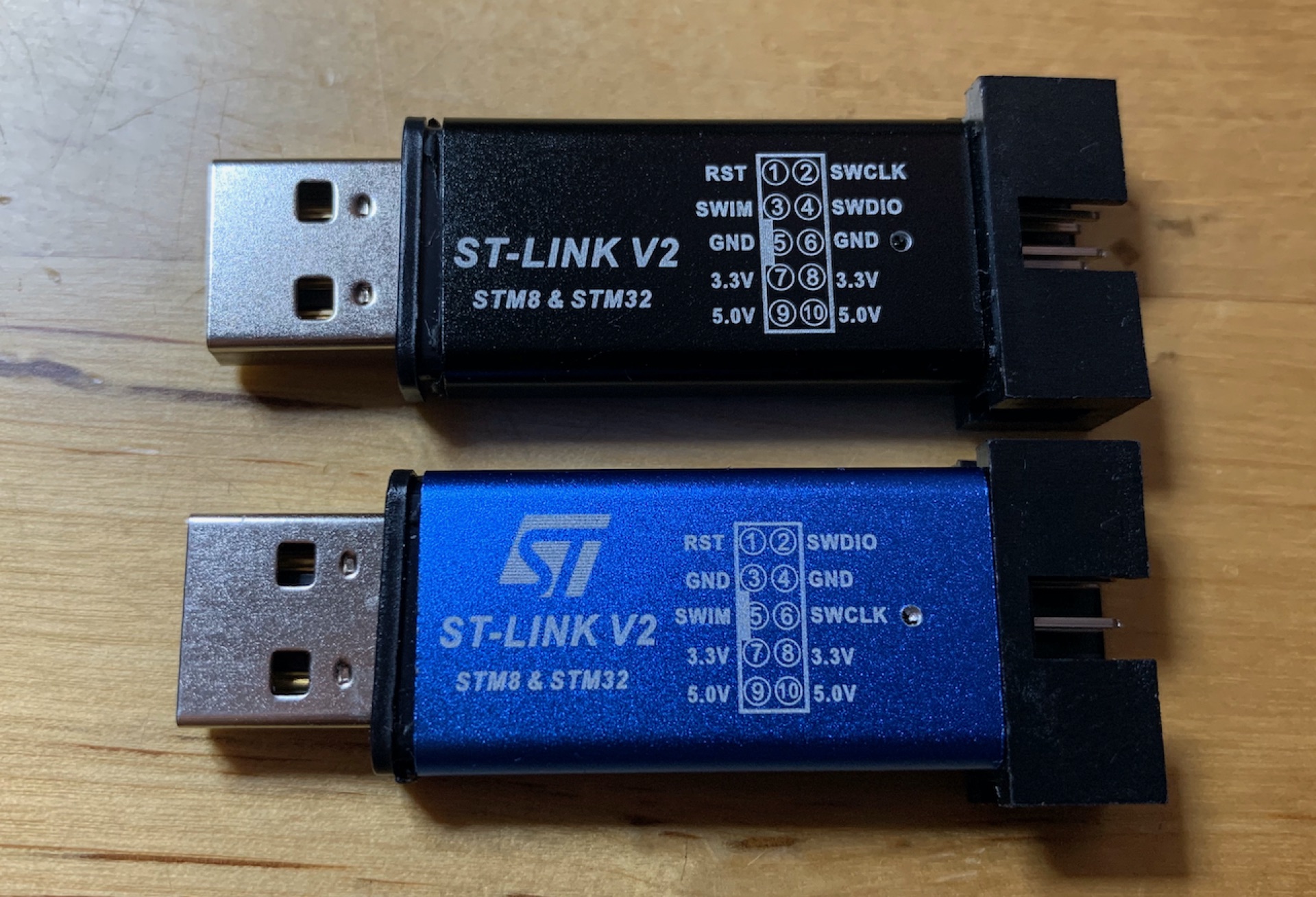
After some further digging through the box in which I store my microcontroller stuff, I found to my surprise another ST-Link/v2 knockoff which I must have purchased some years ago (and since forgotten about it - hi).

Figure 3: Two ST-Link/v2 knockoffs
After swapping the blue ST-Link for the black one, I was suddenly able to connect to the ‘Blue Pill’ development board!
The solution
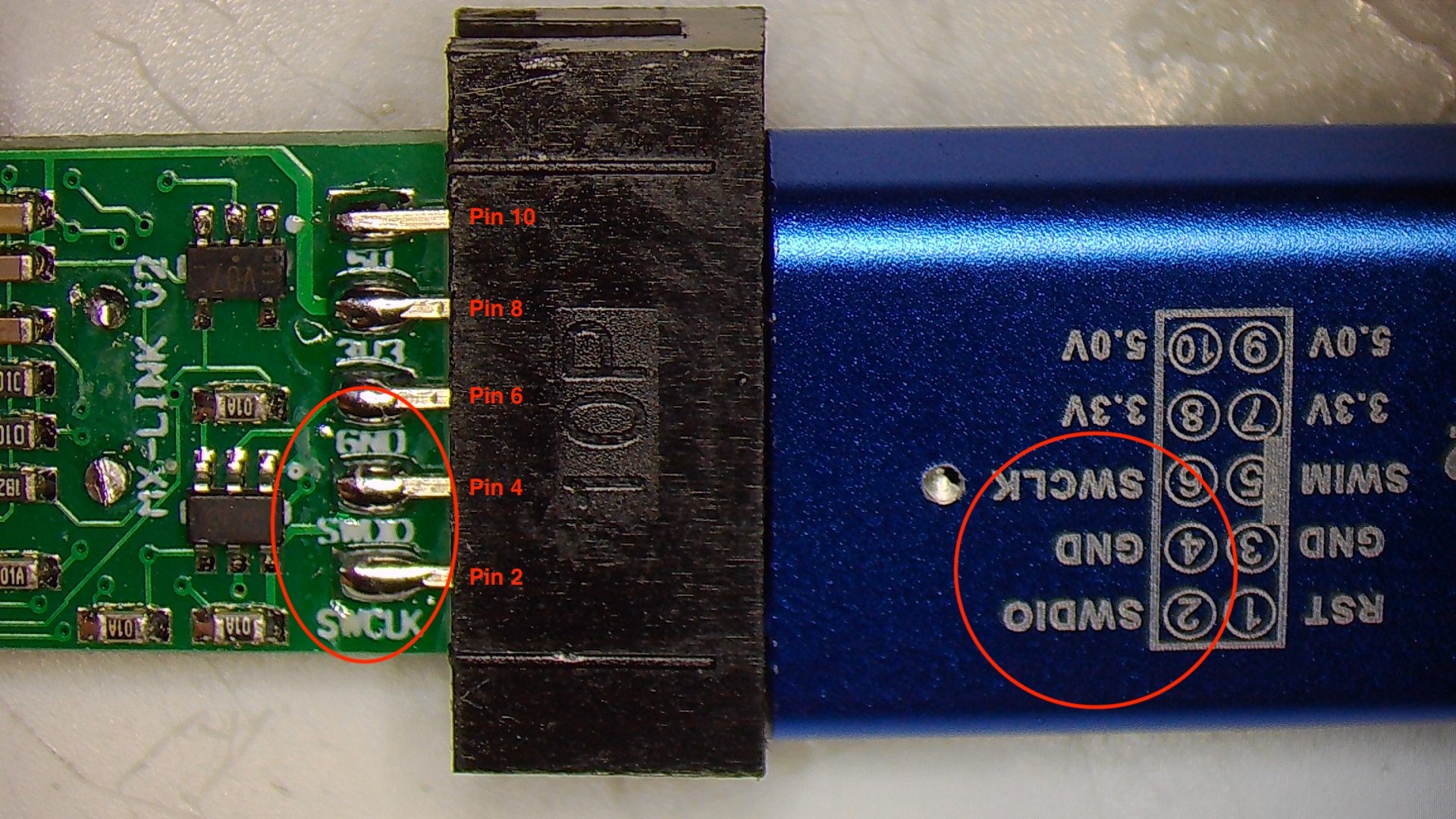
With a working setup, I investigated why the blue ST-Links didn’t work. The most obvious difference is the pin-out diagrams printed on the respective ST-Link knock-off. Opening the blue ST-Link revealed the following:

Figure 5: ST-Link/v2 PCB bottom side
The pin names on the PCB differ from the diagram printed on the ST-Link/v2 enclosure!!!
After re-wiring, the blue ST-Link/v2 also worked as expected.
For the sake of completeness, here the correct pin-out:
| Pin | Row | Name |
|---|---|---|
| 1 | Upper | RST |
| 3 | Upper | SWIM |
| 5 | Upper | GND |
| 7 | Upper | 3.3V |
| 9 | Upper | 5.0V |
| 2 | Bottom | SWCLK |
| 4 | Bottom | SWDIO |
| 6 | Bottom | GND |
| 8 | Bottom | 3.3V |
| 10 | Bottom | 5.0V |
Bottom line
Out of curiosity, I checked Amazon, eBay, and a few of the Chinese trading platforms and to my surprise, almost all of the ST-Link/v2s shown have the wrong pin-out diagram printed on the enclosure. I hope that the manufactures will correct the diagram in the future. In the meanwhile, I hope this article was helpful and saved you from falling into the same trap 😜.