FA-SDR-TRX part #1 – Systems View
The FA-SDR-TRX is an all-band low-cost software defined radio. The FA-SDR-TRX was created by Harald DL2EWN and described in an article series in the German Ham Radio Magazine Funkamateur. After the big success of the single band kits like Softrock, SDR4080, or Genesis, the FA-SDR-TRX is the next step in the evolution of SDR kits. Thanks to the support of Harald I’m able to provide a detailed description of the concept behind FA-SDR-TRX.
Other posts in this series:
FA-SDR-TRX - part #1 - a Systems View
FA-SDR-TRX - part #2 - the Receiver
FA-SDR-TRX - part #3 - the Transmitter
Motivation
Harald, DL2EWN’s motivation was to create a software defined radio platform that can receive and transmit on all amateur HF bands (160m-10m). The receiver shall have very good characteristics and the transmitter shall be capable to deliver a clean 1 Watt signal for serious usage on the bands. The whole transceiver shall be located on a single PCB but maintaining the flexibility to use the receiving part without having assembled the transmitting path. Having in mind that the FA-SDR-TRX will be assembled by a lot of Hams with different skills, reproducibility of its performance was an important requirement. Even if the kit contains SMD components, all of them will be pre-mount on the PCB to simplify assembly. A modular design and the use of inexpensive and widely available components shall ensure an affordable price.
Concept
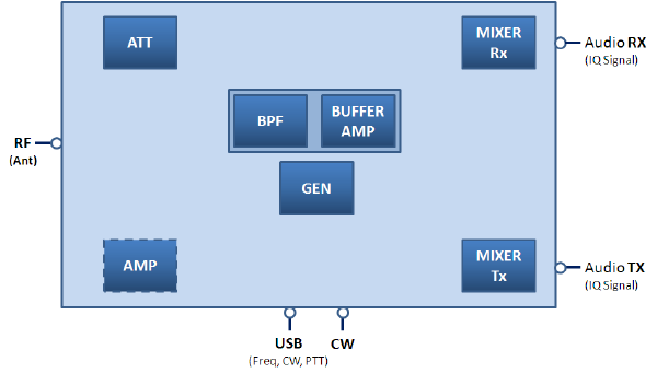
The fundamental components of the FA-SDR-TRX are illustrated in the drawing below:

The transceiver consists out of the 7 major components:
- ATT – Attenuator
- BPF – Band Pass Filter / Preselector
- BUFFER AMP – Buffer Amplifier (actually it’s part of the preselector)
- GEN – Signal Generator
- MIXER Rx – Quadrature Sampling Detector (QSD)
- Mixer Tx – Quadrature Sampling Exciter (QSE)
- AMP – an optional 1Watt amplifier
The FA-SDR-TRX provides the following interfaces:
- RF Input – Antenna Signal
- Audio RX – Receiving stereo IQ signal – to be connected to LineIn on the Soundcard
- Audio TX – Transmission stereo IQ signal – to connect to LineOut on the Soundcard
- USB – Tuning the Frequency, CW Signal, and PTT
- CW – External CW Key
Shared components
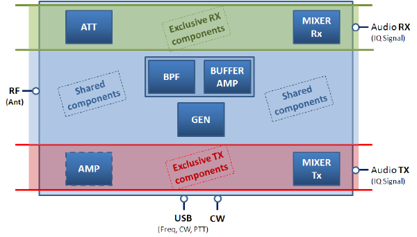
The FA-SDR-TRX is sharing some of its components between the receiving and the transmitting path. The following drawing shows the grouped components.

Attenuator and RX Mixer are exclusively used by the RX path. Amp and TX Mixer are used exclusively by the TX path. Bandpass filter, Buffer-Amp, and the Signal Generator however are shared components. They are used by both, the RX and TX path.
Block Diagram
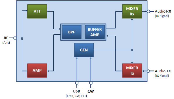
This block diagram shows the interaction between the components:

Please note that this is a simplified view
FA-SDR-TRX Receiver
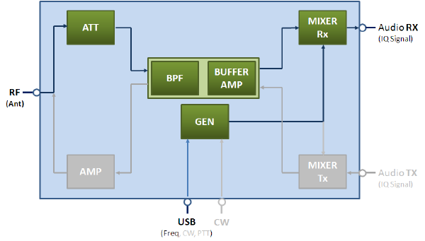
So, let’s get into more detail. We’ll start with the receiving part of the FA-SDR-TRX. Meanwhile, the Transmission path is greyed out.

The RF signal is fed into an attenuator. Even if the overall performance of the receiver is very good (IP3 >15dBm [actually IP3 would be +28dBm without the buffer amp] and IMDR3 >90dB) an attenuator was implemented to avoid overloading the receiver with too strong signals (e.g. 49m band). Passing the attenuator, the Signal is filtered in an adjustable bandpass filter/preselector. The following buffer amp (SGA5289) ensures a 50Ohm match to the following stage and suppresses unwanted radiation of the QSD’s switching frequency. The amplifier is an MMIC with 13dB gain. The following Mixer is a Quadrature Sampling Detector providing the IQ baseband signal for the soundcard. Several classical switching-ICs (FST3253, MAX4614, 74HC4066) were tested. Then, still, quite unknown 74LVC4066 showed the best results. Making maximum use of existing components, the proven FA-SY1 generator (Si570) was implemented. The FA-SY1 provides a USB interface to tune the frequency.
FA-SDR-TRX Transmitter
The next illustrations show the transmission path of the FA-SDR-TRX.

With the help of a PC and its soundcard, an IQ (stereo) Signal is fed into the TX-Mixer. The frequency of the Quadrature Sampling Exciter is tuned with the Si570 generator (the same which is used by the RX). At this stage, the output power of the QSE is about 1mW. Unwanted Harmonics and intermodulation products are suppressed by the passive preselector. The buffer amp boosts the “cleaned” signal to 10mW. Intermodulation products are with -56dBc well below the carrier. Image frequency suppression is with -60dBc also ok. Before sending the signal on the air, the FA-SDR-TRX allows the use of a 1-Watt amplifier (RD00HHS1 MOSFETs). This amplifier is optional and realized with an additional PCB which can be plugged in the FA-SDR-TRX PCB. However, this Amplifier is not part of the FA-SDR-TRX kit. It has to be purchased separately.
Stay tuned
I hope that this article gave you an overview of the concept behind this all-band software defined radio. kit. In a further article, I’ll explain the mentioned components in greater depth. Maybe I will also be able to provide the schematics, but this has to be authorized by the publisher Funkamateur.
Kits will be available in January 2010. Orders are already taken. If you are interested, you might consider placing an order. Usually, the first batch of Funkamateur kits is sold out early after the release. The kit is called BX200 and costs 124€ (approx. 180 USD). Please note that the Si570 Signal Generator (FA-SY1) and the 1-Watt Amplifier (not available so far) have to be purchased apart.