
Replacing Yaesu FT857 IF filters
Recently my Yaesu FT857 became deaf. It turned out that the plastic enclosure of the FT857 filters over time consented to moisture which ruined the filters. In this post, I’ll show you how I replaced the filters and brought the radio back to life.
I own a Yaesu FT857 for some years now. I haven’t used the radio much. A few weeks ago I wanted to do some tests with a new antenna, but when I took the radio out of the box and connected it to the antenna it felt pretty deaf, and all I heard were static crashes. Even after disconnecting the antenna, the “static” crashes remained. So obviously something was wrong.
I was a bit surprised because so far the radio spent most of its life in the OEM’s box.
So it was time for a visual inspection of the radio’s inners. My eyes felt pretty soon on the IF filter stage. On top of the plastic housing of the 455kHz filters (CF5, CF3, and CF2) sweat beads and some sort of crystals were visible.

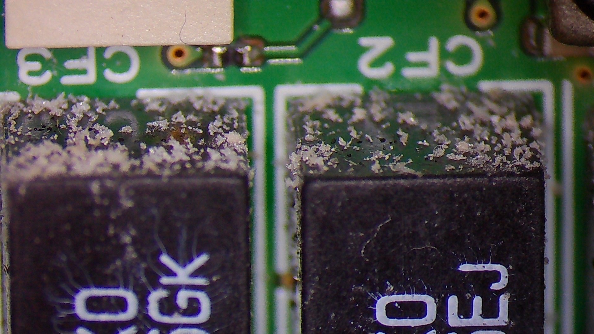
The pictures above show the “sweat beats” and crystals formed on the filter’s plastic enclosure.
Fortunately, replacement filters are inexpensive (less than 10€) and commonly available from large electronics distributors or eBay.
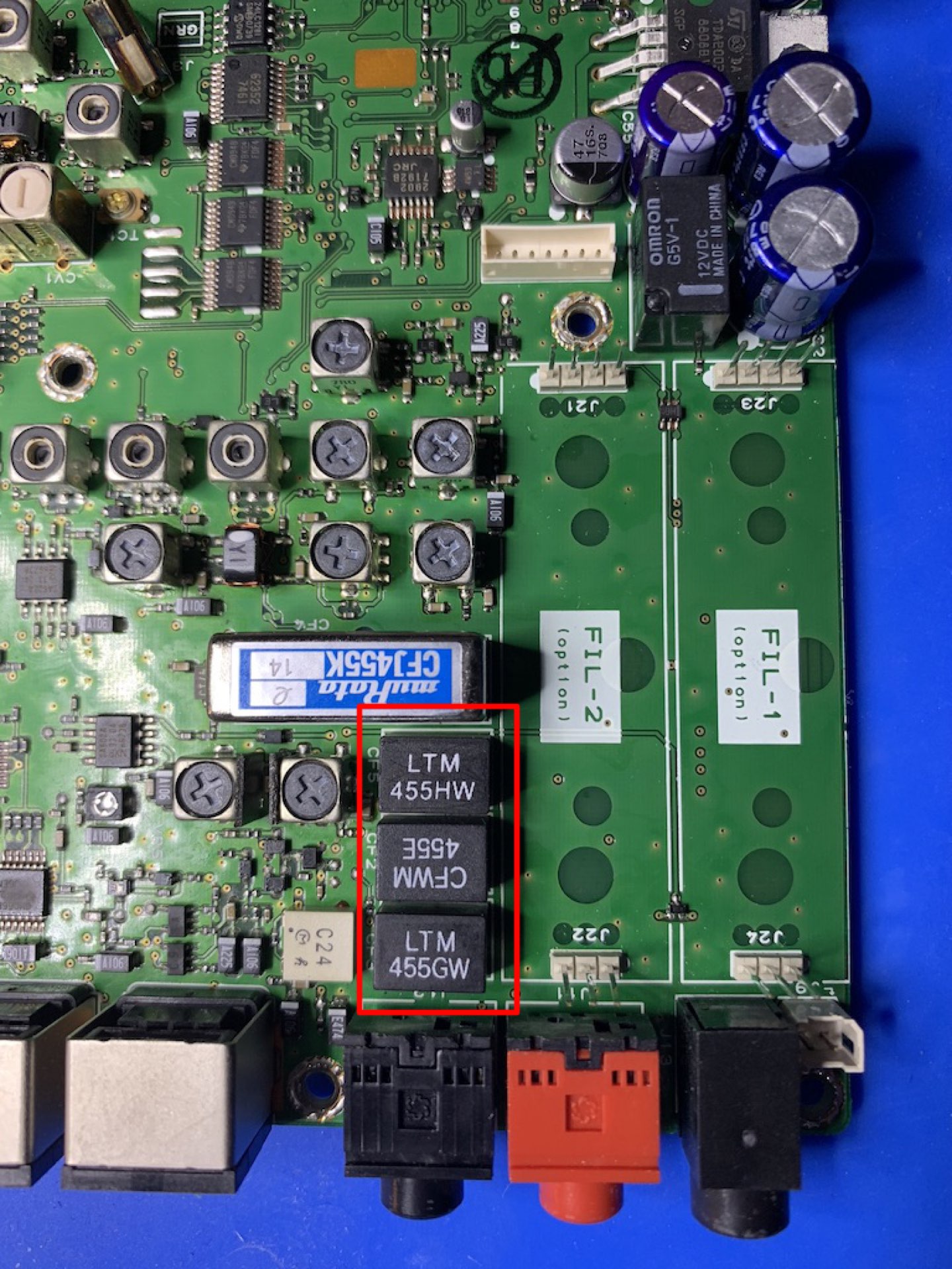
I decided to replace the three TOKO filters with pin-compatible filters from Murata.
- CF3: TOKO A55GK -> Murata LTM455GW
- CF2: TOKO A55EJ -> Murata CFWM455E
- CF5: TOKO A55HL -> Murata LTM455HW
How to replace the filters
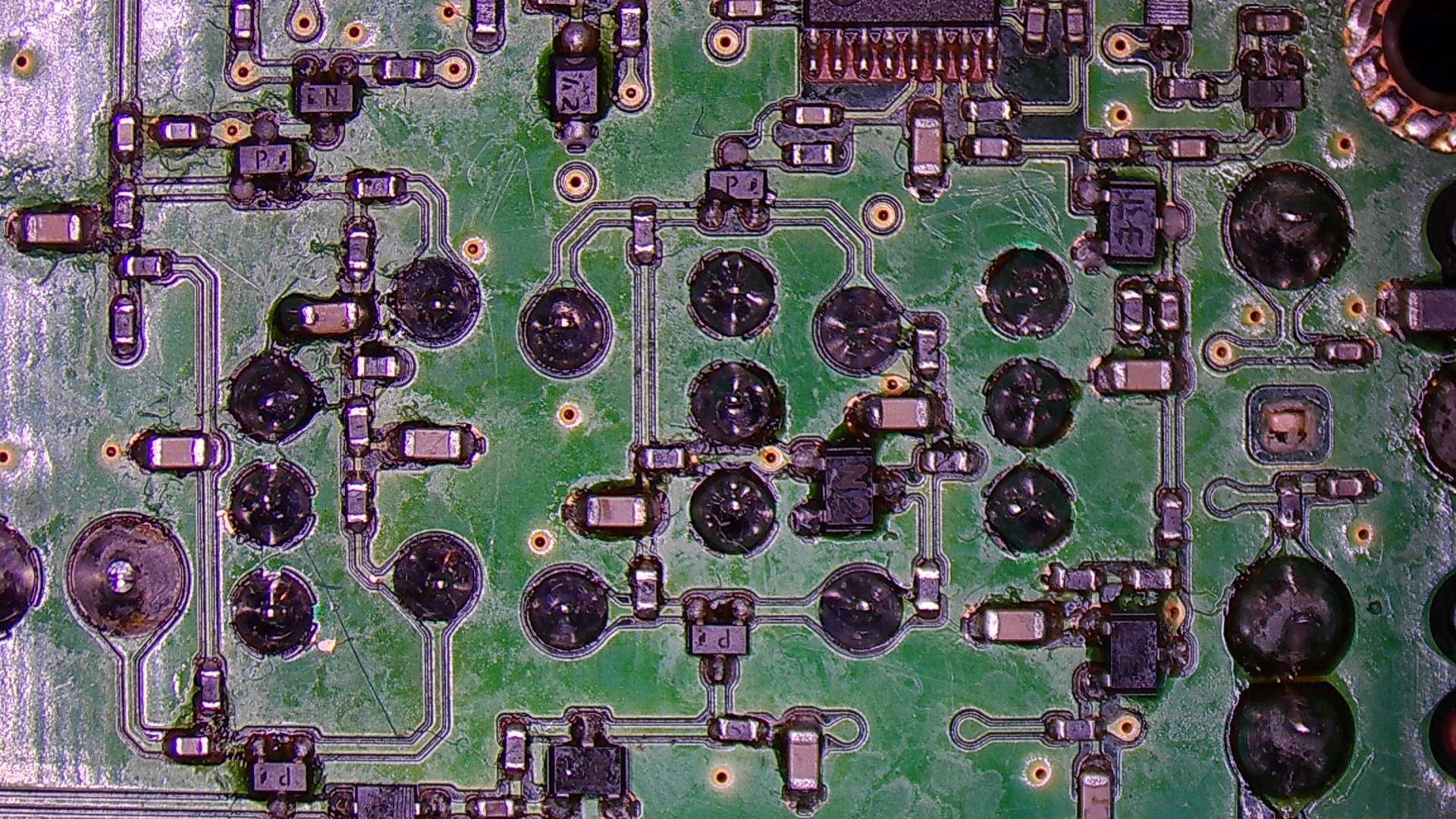
Just a word of caution: Soldering on the backside of the PCB is a bit tricky since small SMD components (mostly 0603) are located nearby. You need good magnification glasses or a microscope. Below is a picture of the lower part of the PCB, marking the solder points of the three filters.

Since all modern electronics is now soldered with lead-free solder it’s a bit cumbersome to remove it. I usually add some 60/40 solder and then remove it with a solder wig. Adding flux also helps.
After removing the solder I was able to pull out the old filters.
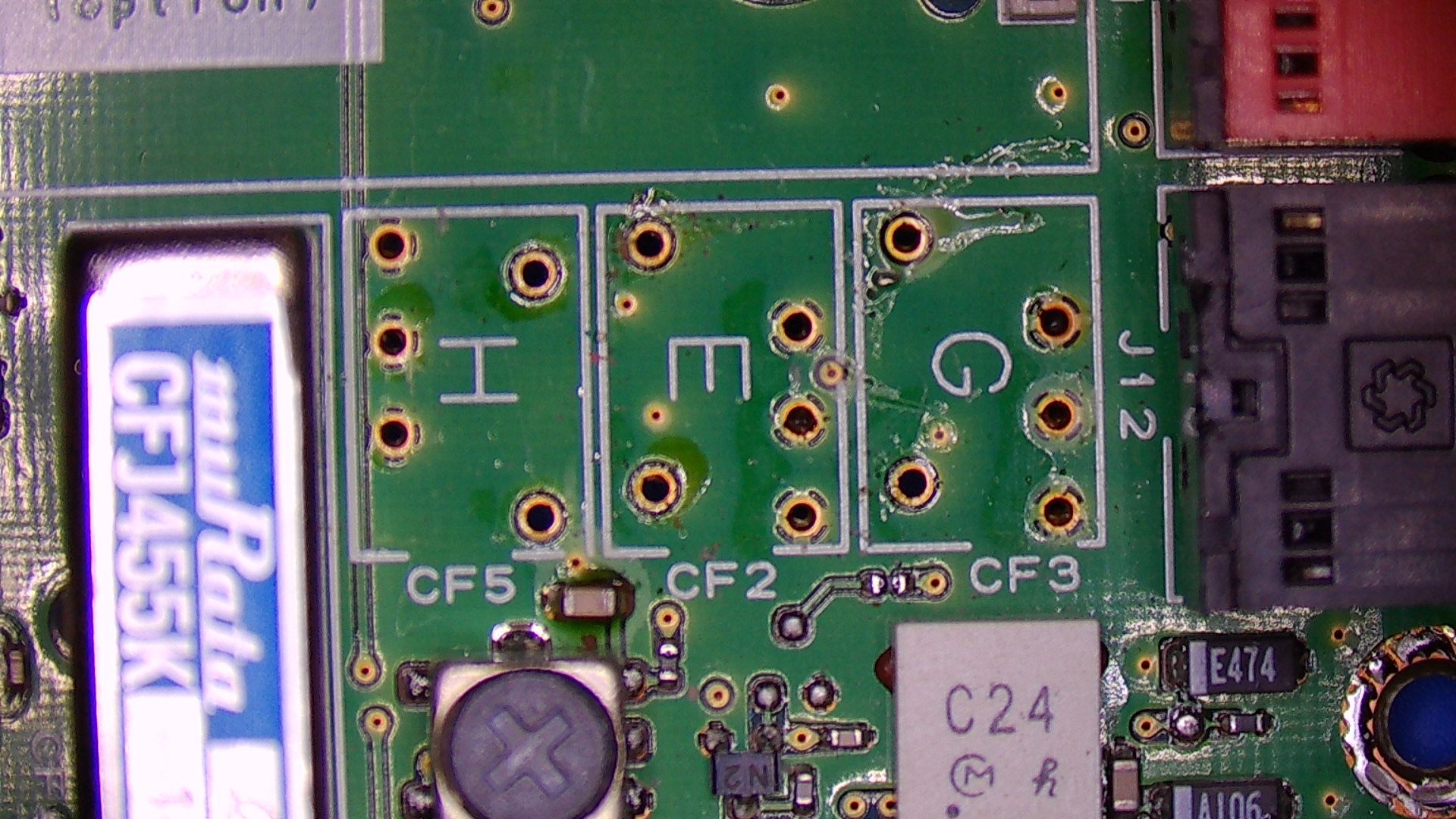
The position of each filter is marked with a letter that corresponds to the appropriate filter.
- G: 455GW
- E: 455E
- H: 455HW
After soldering the new filters, I removed the flux with Isopropanol and waited a couple of hours until the alcohol was evaporated. The last thing you want to have is a shorted circuit somewhere on the PCB ;-)
The picture above shows under high magnification the lower part of the PCB, cleaned and with new filters equipped. The whole procedure took about 90 minutes.
Root cause
So what after all is the root cause of the failure? Well, you can find different speculations on the web. Some say that the plastic of the filters was just bad, others believe that there is a design flaw in the circuit and that the DC bias voltage killed them. There are even modifications available where folks break out vias and insert additional DC blocking caps.
I don’t think that such drastic modifications are necessary. As The Radio Mechanic pointed out in this Youtube video on this topic, non of the datasheets tell that DC voltages will harm the filter. So probably the bad plastic theory is right. Time will tell… I got another spare set of filters, just in case.
Finally: Here is The Radio Mechanic’s video, which is worth watching if you are planning on changing the IF filters.
